
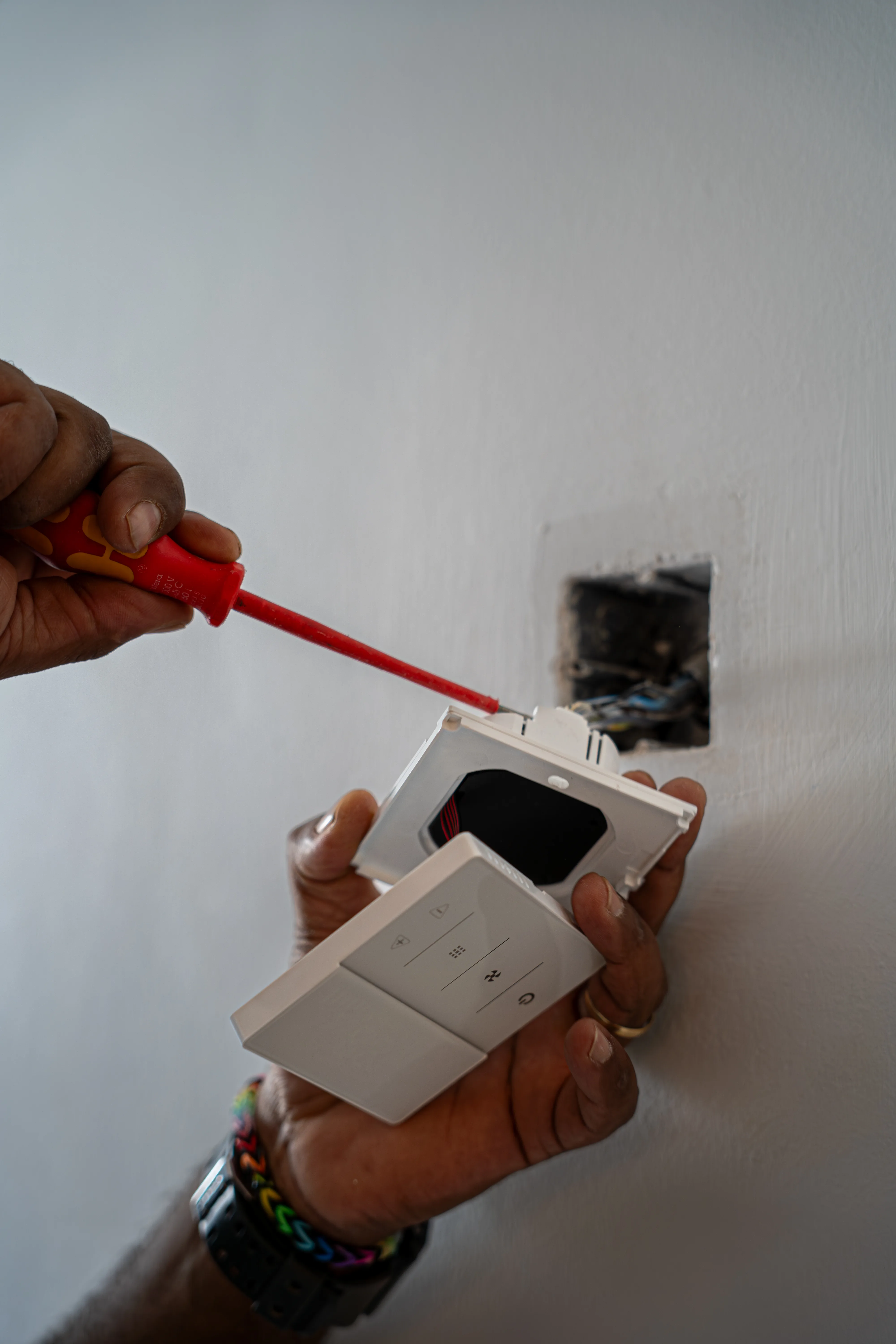
Where to install it
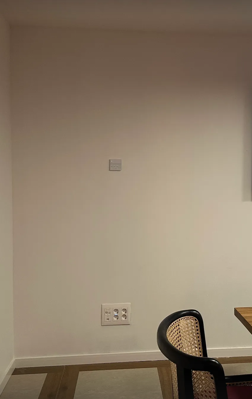
Install the Voltic FrostLine inside the room, following these rules:- At a height of 1.5 m from the floor
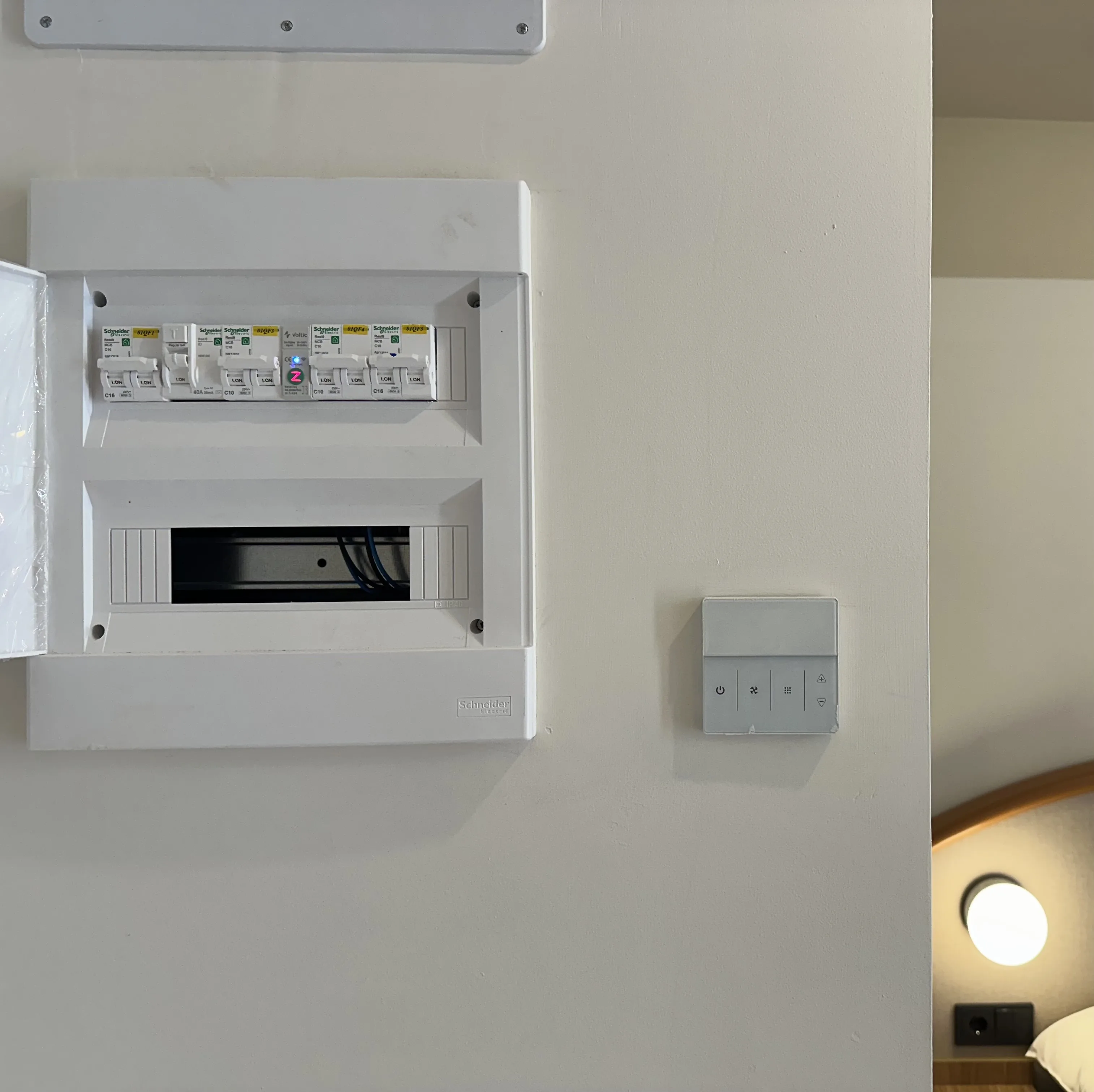
- Away from windows, doors, radiators, splits, and exterior walls
- Always connected to a 24h electrical line (not controlled by a contactor or key card)
- On a standard flush-mounting box of 75x75x35 mm (compatible with 86x86 frame)
- Do not install in corners, behind furniture, or in places where air circulation is obstructed
Connection and wiring
- Power supply: 230V AC / 50 Hz (exclusively via 230V line, no batteries required)
- Maximum load: 3A
- Digital outputs:
- Valve or valves: according to the installation configuration
- Fan speeds: V1 / V2 / V3
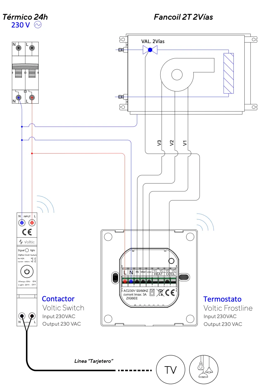
The diagram shown is for a 2-pipe installation. Do not reuse it as a template for 4-pipe or combined underfloor-heating installations; check the compatibility guide.
Hubs and pairing
FrostLine can pair with a VolticHub for management in app.voltic.es, or with a Tuya-compatible Zigbee Hub for use with Tuya Smart / Smart Life. The inclusion process and available features depend on the Hub and its firmware.For a standalone installation, choose the Hub and platform before mounting the thermostat. Do not pair the device with a second platform without following the relevant migration or unpairing procedure.
Standalone installation
If FrostLine is installed in a home or outside a hotel kit:- Identify the device version, fan coil diagram, and Hub you will use.
- Check scenario compatibility and prepare the protections.
- Mount and wire the device with the circuit isolated, following the validated diagram.
- Pair FrostLine with the VolticHub or Tuya Hub and test each output before closing the installation.
Mounting
- Direct mounting on universal flush-mounting box
- Screws included in the kit
- Ensure leveling for correct front panel fitting
Placement examples
Common mistakes
Tilted mounting
Tilted mounting
A tilted mounting creates poor contact with the box and can cause incorrect temperature readings. Make sure the thermostat is perfectly level.
Incorrect output wiring
Incorrect output wiring
If the digital output wiring is incorrect, the valve or fan will not respond. Verify the connection diagram before energizing.
12V or 24V valves connected
12V or 24V valves connected
The Voltic FrostLine is only compatible with 230V valves. Connecting low-voltage valves may damage the device.
Post-installation checks
1
Verify the power supply
Confirm that the thermostat receives 230V at the input terminals and that the screen responds correctly.
2
Test the valve and fan
Verify that the thermostat controls the valve and fan speeds according to the active mode.
3
Sync with the platform
Confirm on the selected platform (Voltic or Tuya Smart / Smart Life) that the device is paired and reports temperature correctly.